This section updated 14 April 2007
1 each Power Supply Case with hardware
1 each internal shield
The coils for the 15 meter filter use 3/4 inch schedule 40 PVC pipe as the coil form. The form dimensions are listed below.
| Coil # | Pipe Size | Pipe Length | # Turns | Winding Length |
| L1-3 | 3/4 inch | 2 inches | 11-1/2 | 1.10 inches |
#14 solid conductor insulated wire.
3 each 54 inches
C1, C5 – 2 each 12 pf 3 KV Panasonic P/N ECC-A3F120JGE
C2, C4 – 2 each 100 pf 1KV Panasonic P/N ECC-A3A101JGE, 1 each 12pf
1KV
Panasonic P/N ECC-A3A120JGE
C3 – 1 each 12pf 3 KV Panasonic P/N ECC-A3F120JGE, 15 pf 3 KV
Panasonic P/N ECC-A3F150JGE
Mounting hardware 4-40 brass
3 each 1-1/4 machine screws
16 each ¼ machine screws
22 each nuts
5 each washers
2 each ground lug
Connector labels
This section updated 16 April 2007
The coils for the 15 meter filter use 3/4 inch schedule 40 PVC pipe as the coil form. The form dimensions are listed below.
The coils are wound using #14 solid conductor insulated wire.
| Coil # | Pipe Size | Pipe Length | # Turns | Winding Length |
| 1, 2, 3 | 3/4 inch | 2 inches | 11-1/2 | 1.10 inches |
The length of the actual coil winding is for reference purposes.
Prepare the case.
Prepare the coils. Note L2 needs a little extra wire at the C2 end.
Mount the connectors, coil hardware, and lugs.
Mount L2 first so you can swing it to get the internal nut in place.
Mount L1 and L3.
Prepare C2 and C4 by twisting the leads and soldering the entire length.
Attach C4 to the lug at the bottom of the case and form the other end lead into a terminal as a connection point for C3 and C5.
Attach C2 to the lug on the bottom of the case. The coil lead is bent down to meet C2 and C1. Keep the coil lead parallel to the form to retain the coil turns. Then bend on a large radius down to the capacitors.
Mount the shield to two sides of the cover along the center line with four 4-40 x ¼ inch brass machine screws and nuts so that it separates the input and output coils. Drill clearance holes in the base and tap holes in the shield to secure it in place when the cover is installed.

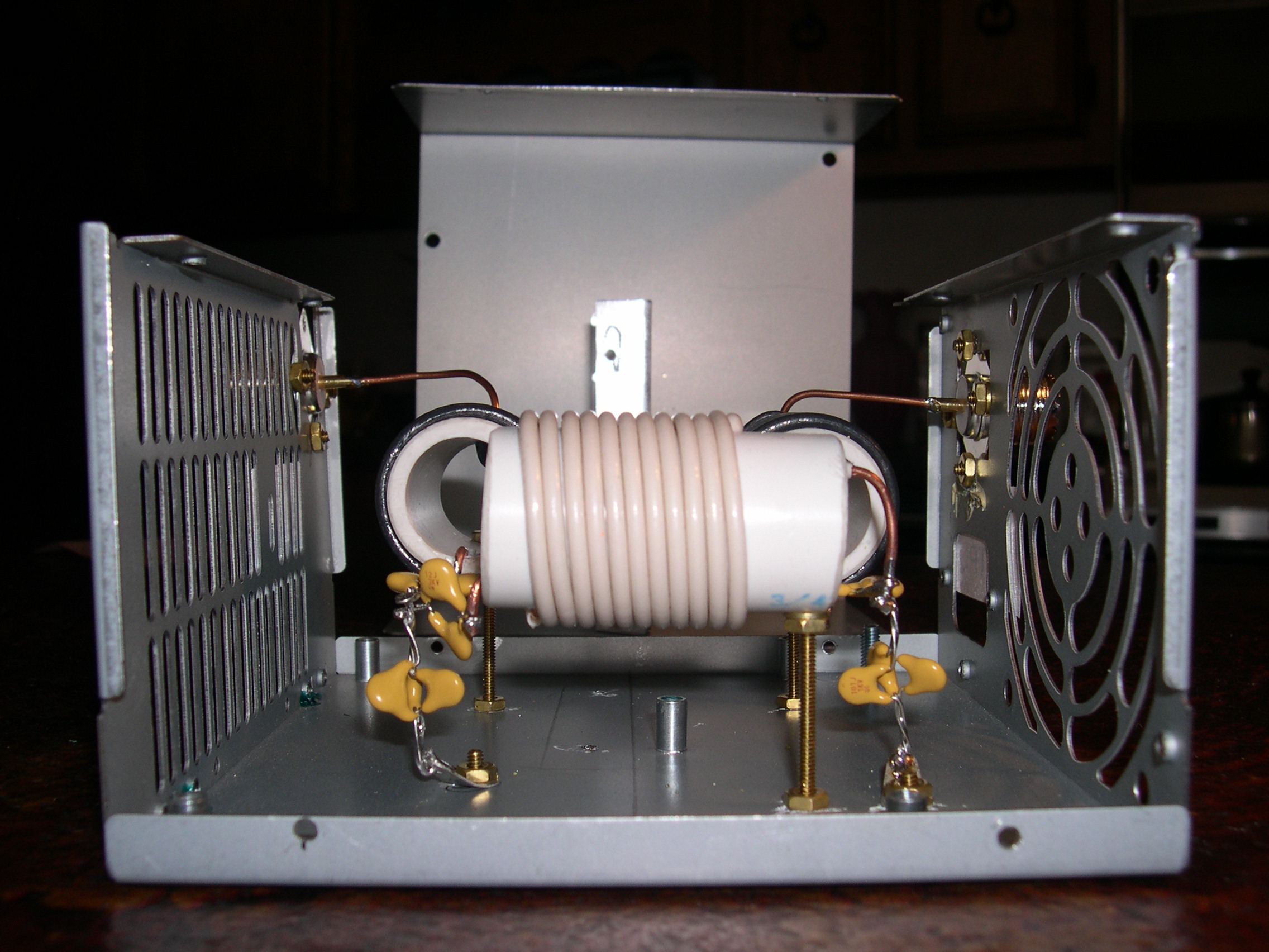
Figure 1: Capacitor wiring and middle coil lead. [high resolution version]
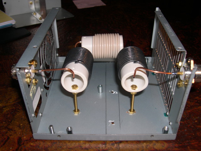
Figure 2: Connector end of filter showing the input and output wire leads make from the coil wire. Be sure to leave enough wire for the leads when winding the coils. [high resolution version]
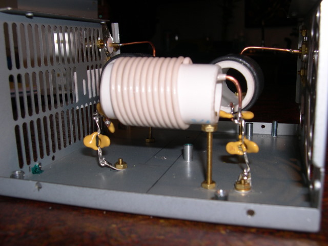
Figure 3: Deteail of middle coil lead wiring. [high resolution version]
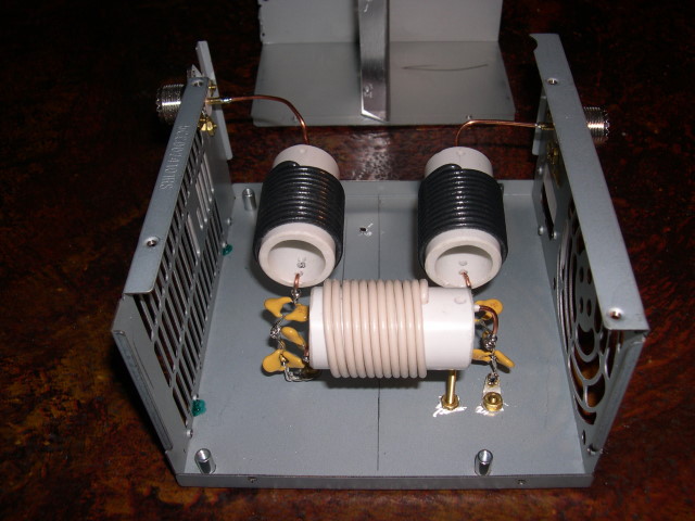
Figure 4: View of capacitor wiring. Note the training of the middle coil leads. [high resolution version]
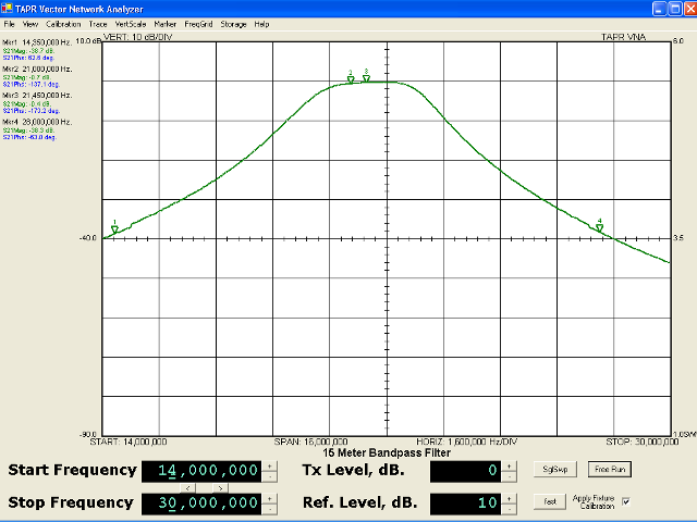
Figure 5: Attenuation vs. frequency [full resolution version]
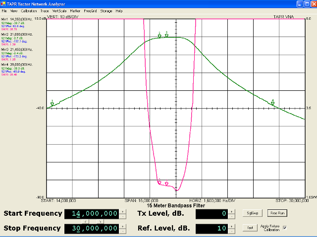
Figure 6: SWR vs. frequency [full resolution version]
Updated $Date: 2007-04-19 02:36:41 +0000 (Thu, 19 Apr 2007) $