This section updated 31 August 2008
1 each Power Supply Case with hardware
1 each internal shield
The coils for the 20 meter filter use three-quarter inch schedule 40 PVC pipe as the coil form. The form dimensions are listed below.
| Coil # | Pipe Size | Pipe Length | # Turns | Winding Length |
| L1-3 | 3/4 inch | 2-1/4 inches | 14 | 1.40 inches |
#14 solid conductor insulated wire.
3 each 60 inches
C1, 5 – 1 each 47 pf 3 KV Panasonic P/N ECC-A3F470JGE
C2, 4 – 2 each 150 pf 1KV Panasonic P/N ECC-A3A151JGE, 1each 18pf all 1KV Panasonic P/N ECC-A3A180JGE
C3 – 1 each 22pf 3KV Panasonic P/N ECC-A3F220JGE, 33 pf 3KV Panasonic P/N ECC-A3F330JGE
Mounting hardware 4-40 brass:
3 each 1-1/2 machine screws
19 each ¼ machine screws
23 each nuts
5 each washers
2 each ground lug
Connector labels
This section updated 3 March 2007
The coils for the 20 meter filter use 3/4 inch schedule 40 PVC pipe as the coil form. The form dimensions are listed below.
The coils are wound using #14 solid conductor insulated wire.
| Coil # | Pipe Size | Pipe Length | # Turns | Winding Length |
| 1, 2, 3 | 3/4 inch | 2-1/4 inches | 14 | 1.40 inches |
The length of the actual coil winding is for reference purposes.
Prepare the case.
Prepare the coils.
Mount the connectors, coil hardware, and lugs.
Mount L2 first so you can swing it to get the internal nut in place.
Mount L1 and L3.
Prepare C2 and C4 by twisting the leads and soldering the entire length.
Attach C4 to the lug on the side of the case and form the other end lead into a terminal as a connection point for C3 and C5.
Attach C2 to the lug under L2. It is best to attach and solder C2 with the lug loose and away from the coil since the heating will melt the washer into the form loosening the coil. After soldering tighten the lug retaining nut. The other choice is to solder the capacitor to the lug before mounting. The span of this capacitor needs all the length so if pre-soldering to the lug use the minimum necessary.
Mount the shield to two sides of the cover along the center line with four 4-40 x ¼ inch brass machine screws and nuts so that it separates the input and output coils. Drill clearance holes in the base and tap holes in the shield to secure it in place when the cover is installed.
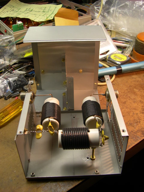
Figure 1: Capacitor and middle coil end of filter. Note the use of the mounting bolt and lug on side of case to reduce the lead length of the shunt capacitor ground. [high resolution version]
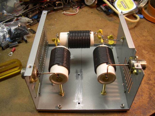
Figure 2: Connector end of case showing coil to input and output connectors. [high resolution version]
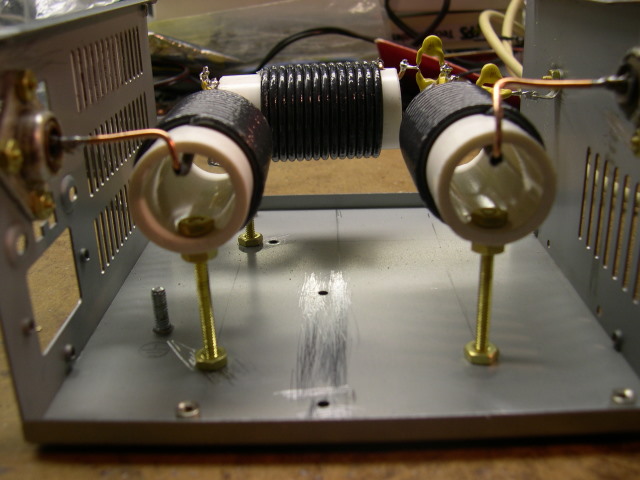
Figure 3: Connector end showing coil mounting detail. [high resolution version]
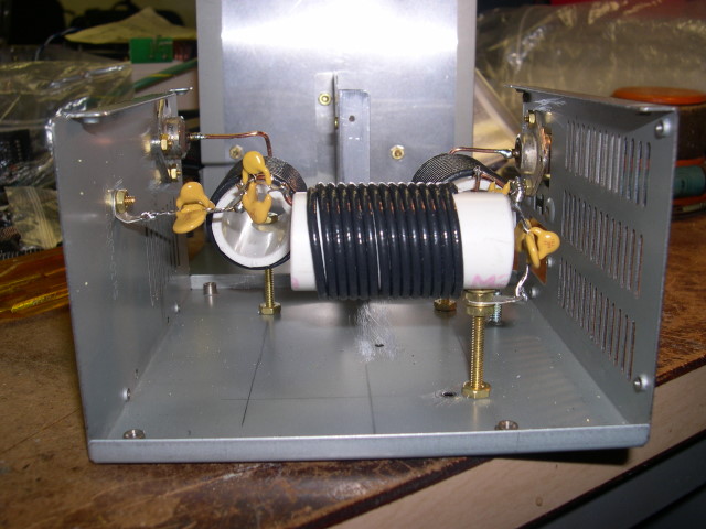
Figure 4: More detail of the capacitor wiring. [high resolution version]
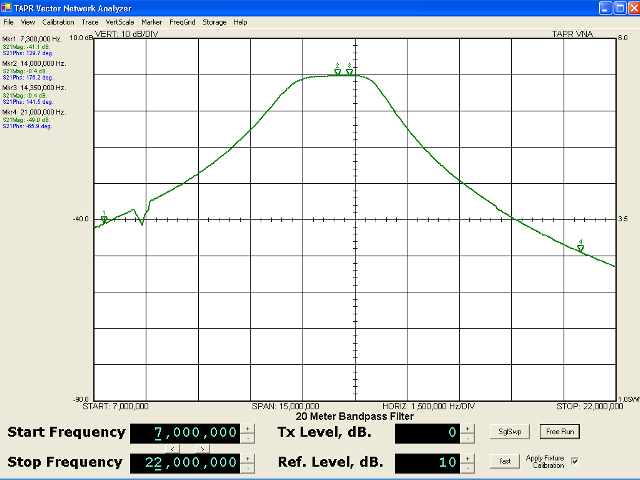
Figure 5: Attenuation vs. frequency [full resolution version]

Figure 6: SWR vs. frequency [full resolution version]
Updated $Date: 2008-08-31 15:20:02 +0000 (Sun, 31 Aug 2008) $