This section updated 16 April 2007
2 each Power Supply Case with hardware
2 each internal shield
The coils for the 80 meter filter use 3/4 inch schedule 40 PVC pipe as the coil form. The form dimensions are listed below.
| Coil # | Pipe Size | Pipe Length | # Turns | Winding Length |
| L1-3,5 | 3/4 inch | 2-1/4 inches | 14.0 | 1.40 inches |
| L4 | 3/4 inch | 2 inches | 7.75 | 0.75 inches |
#14 solid conductor insulated wire.
4 each 60 inches
1 each 36 inches
C1 – 2 each 470 pf 1KV Panasonic P/N ECC-A3A471JGE, 2 each 100 pf 1KV Panasonic P/N ECC-A3A101JGE
C2 – 3 each 390 pf 1KV Panasonic P/N ECC-A3A391JGE, 1 each 150 pf 1KV Panasonic P/N ECC-A3A151JGE
C3 – 5 each 470 pf 1KV Panasonic P/N ECC-A3A471JGE, 1 each 220 pf 1KV Panasonic P/N ECC-A3A221JGE, 1 each 33 pf 1 KV Panasonic P/N ECC-A3A330JGE
C4 – 4 each 470 pf 1KV Panasonic P/N ECC-A3A471JGE, 1 each 100 pf 1KV Panasonic P/N ECC-A3A101JGE, 1 each 68 pf 1 KV Panasonic P/N ECC-A3A680JGE
C5 – 3 each 150 pf 3KV Panasonic P/N ECC-A3F151JGE, 2 each 47 pf 3KV Panasonic P/N ECC-A3F470JGE, 1 each 27 pf 3 KV Panasonic P/N ECC-A3F270JGE
C6 – 3 each 120 pf 3KV Panasonic P/N ECC-A3F121JGE, 1 each 33 pf 3KV Panasonic P/N ECC-A3F330JGE, 1 each 22 pf 3 KV Panasonic P/N ECC-A3F220JGE
Note: these capacitor values differ slightly from the idealized schematic values but are correct.
Mounting hardware 4-40 brass
5 each 1-1/2 machine screws
5 each 3/8 machine screws
21 each ¼ machine screws
31 each nuts
8 each washers
2 each ground lug
Connector labels
This section updated 31 August 2008
The coils for the 80 meter filter use three-quarter schedule 40 PVC pipe as the coil form. The form dimensions are listed below.
The coils are wound using #14 solid conductor insulated wire.
| Coil # | Pipe Size | Pipe Length | # Turns | Winding Length |
| 1, 2, 3, 5 | 3/4 inch | 2-1/4 inches | 14 | 1.40 inches |
| 4 | 3/4 inch | 2 inches | 7-3/4 | 0.75 inches |
The length of the actual coil winding is for reference purposes.
Prepare the case
Mount the two cases back to back oriented to take advantage of the existing holes and the location of the input and output connectors which need to be on opposite sides of the same box (see the reference picture).
Drill the mounting holes for connectors, coil mounting hardware, box to box through holes, and shield. First carefully drill two holes to bolt the two cases together. Four holes total in the corners of the case are recommended for this purpose. Existing holes may be used. Then mark and drill the remaining coil mounting, lead feed-through, and shield mounting holes.
Prepare the coils per the general instructions. Coils L2 and L3 require extra long leads with insulation for the feed-through between the two cases. So do not remove the insulation before the coil is mounted and the lead passed through the case. If the insulation is removed, it is possible to slide a short piece of insulation over the wire before connecting the lead. See next paragraph.
When you wind L2 and L3 leave five (5) inches of wire on the starting (mounting) end of the coil. This wire is used as the connection to the coils and capacitors in the second box. The opposite end needs approximately 1-1/2 inches to accommodate the capacitor connections. Trim all leads as needed after assembly.
Also note in the pictures that L4 has an extended terminal lead to accommodate a loop for mounting to the case. Study photos for relative position and mounting.
For the capacitors that require two or more in parallel prepare the capacitors by gently twisting the leads and soldering the entire length. Be especially careful with the capacitors that require many units in parallel, that the capacitors are correct and that there are no shorts due to parts slipping during twisting of the leads
Mount the connectors, coil supporting hardware, and lugs.
Mount the horizontal coils L1, L2, L3, and L5 first. Passing the leads of L2 and L3 through the holes in the case as the coil is mounted.
Mount the vertical coil L4.
You will need the entire length of the capacitor leads in most cases. Form the leads carefully with long nose pliers making hooks to wrap around coil leads, other capacitor leads or the holes in the ground lugs. C2 is attached to the side of the case with a lug and 4-40 bolt. C4 is attached with a 1-½ inch 4-40 machine screw. Study the photos carefully before proceeding.

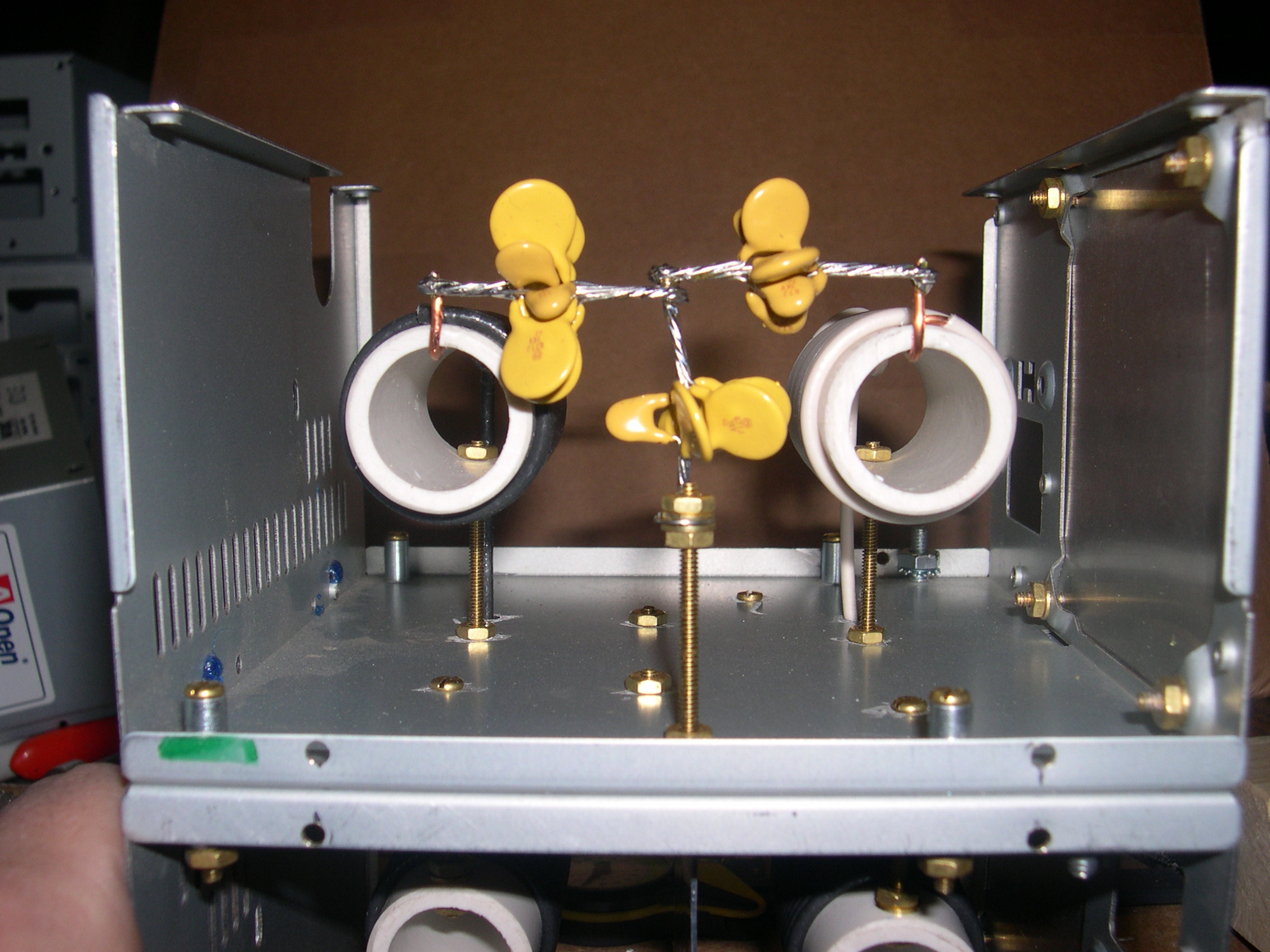
Figure 1: Capacitor and coil view. Middle of filter showing details of shunt capacitor grounding via brass bolt. Note large number of parallel capacitors required. [high resolution version]

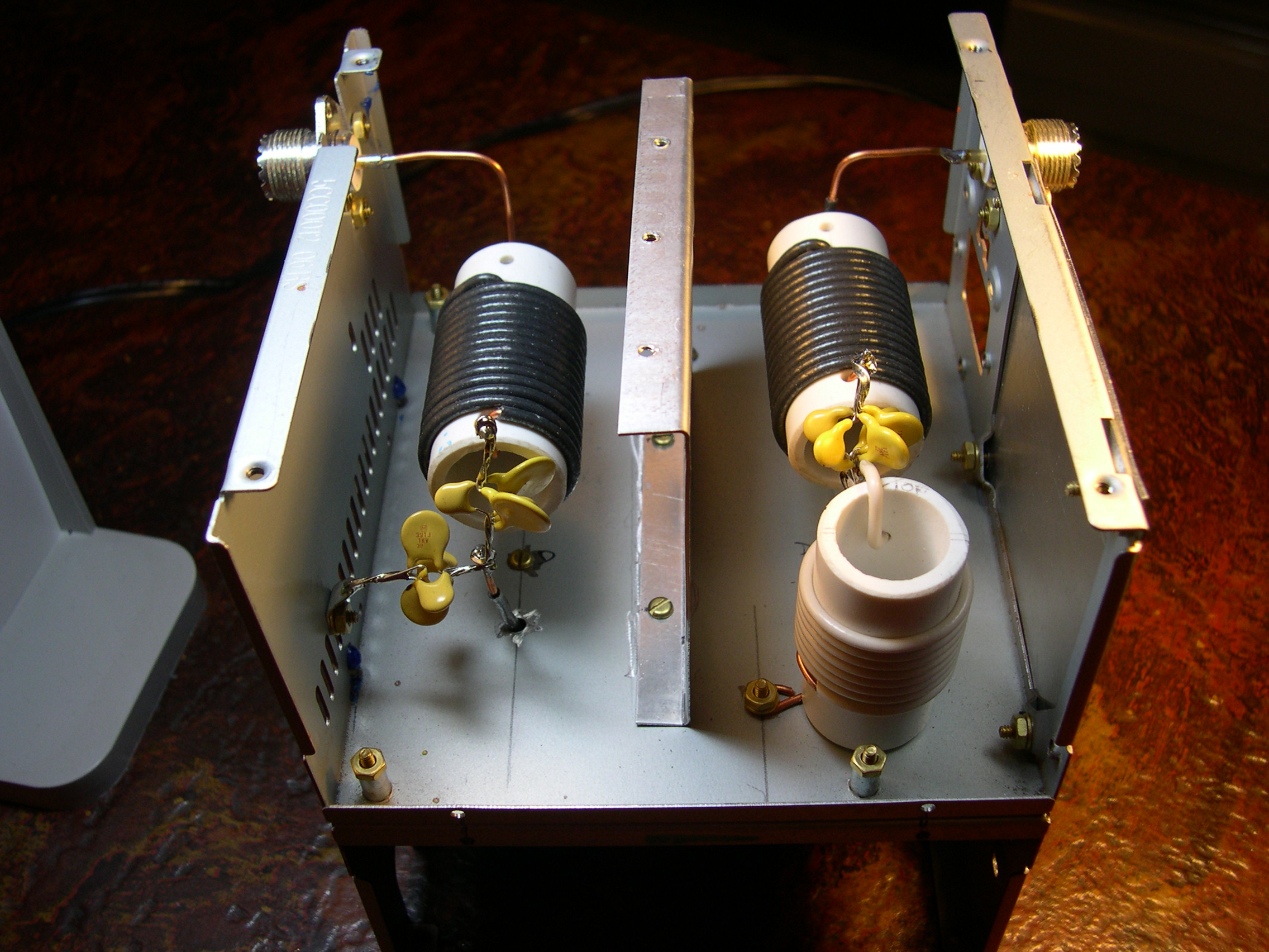
Figure 2: Input/output connector view. This photo shows the input and output connectors and the shunt capacitor and coil. The leads pass thru the center of the case via holes drilled in the case. These feed through wires are insulated with the normal PVC wire insulation. The points in the circuit that are feed through have been chosen to be low voltage points in the circuit so the danger of voltage breakdown is low, but it is advisable to be sure there are no sharp burs on the holes to puncture the insulation on the wires. [high resolution version]

Figure 3: Coil mounting detail. This photo shows the relationship of all the coils. Except shunt coil which is out of site. The input and output coax connectors are out of site at the bottom of the picture. [high resolution version]
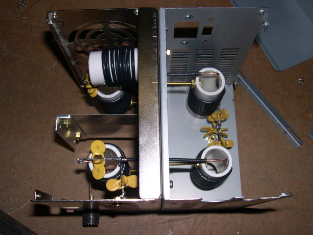
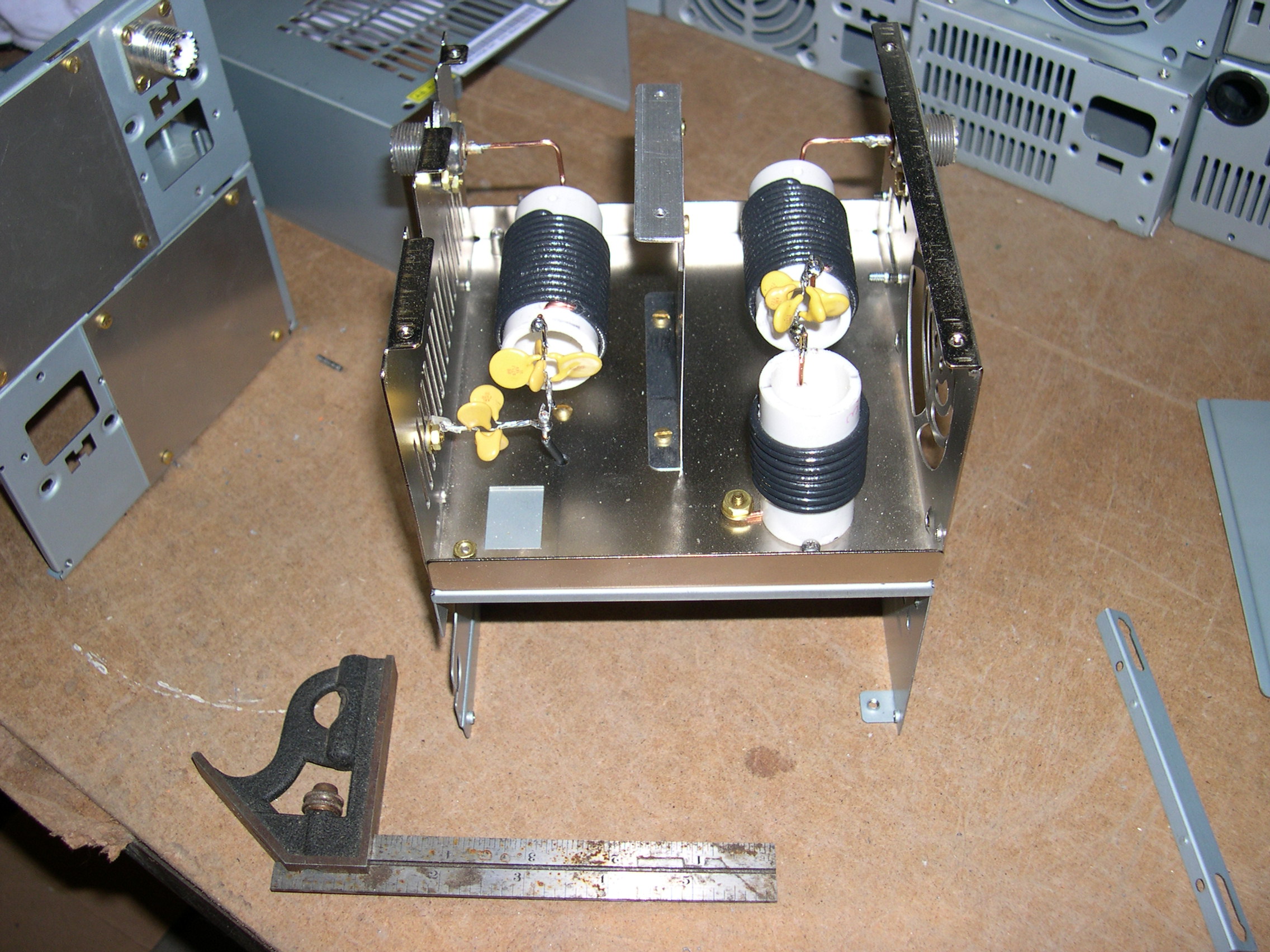
Figure 4: Overall view showing the chassis construction with two PC power supply cases mounted back-to-back. [high resolution version]
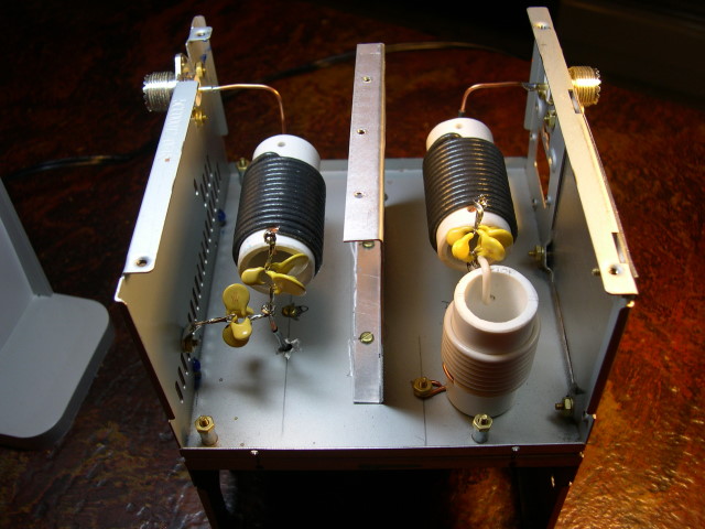
Figure 5: Top (input / output connector side) view showing shield and coil feed-through holes in back-to-back cases. [high resolution version]
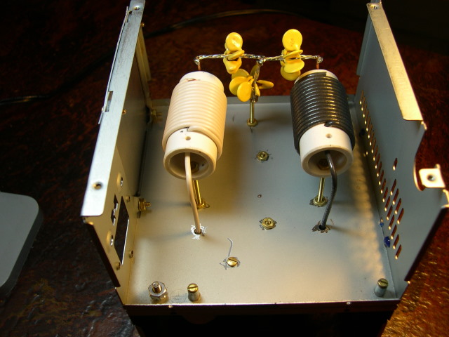
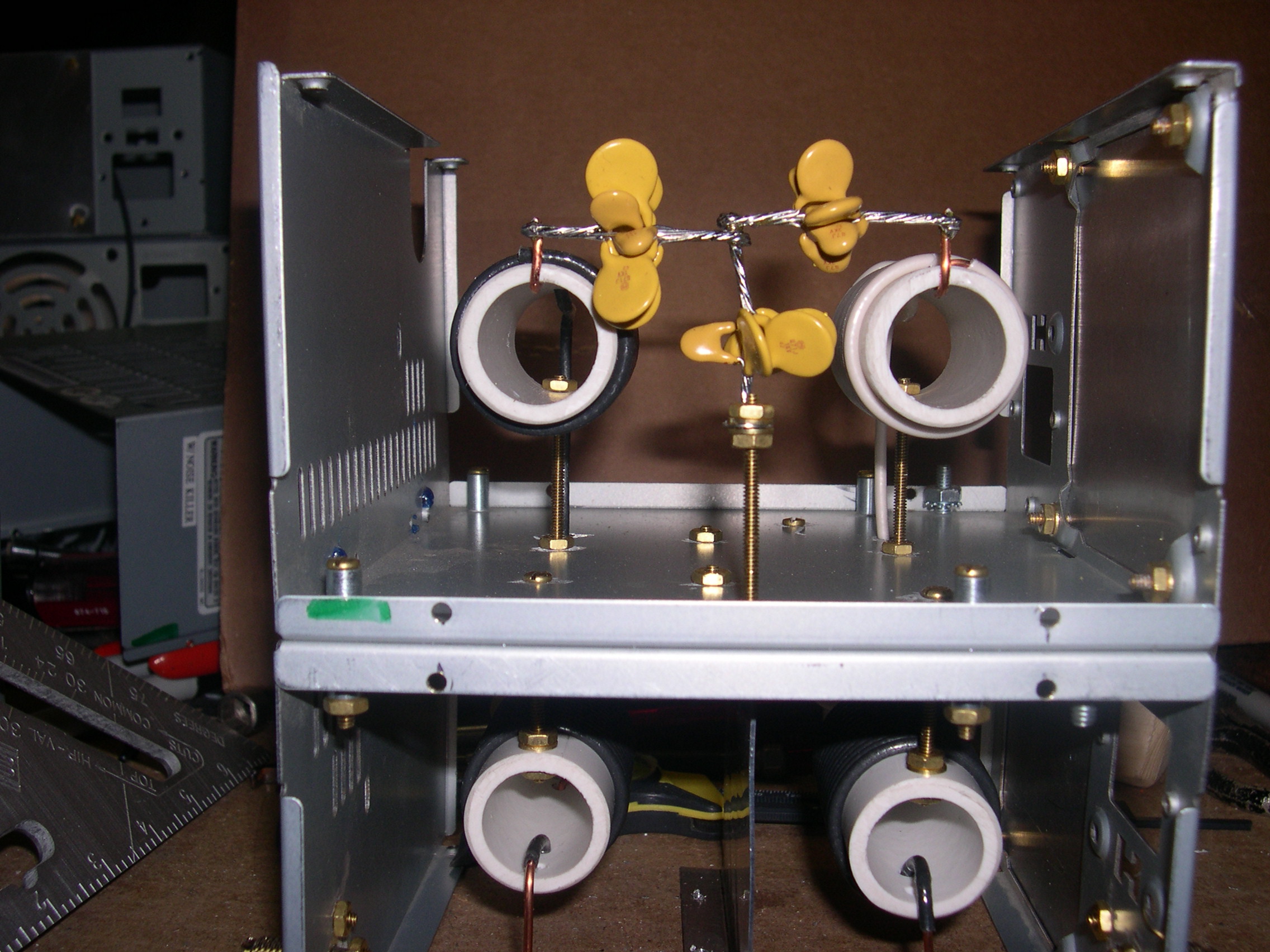
Figure 6: Bottom view showing coil feed-through holes and capacitor detail. [high resolution version]
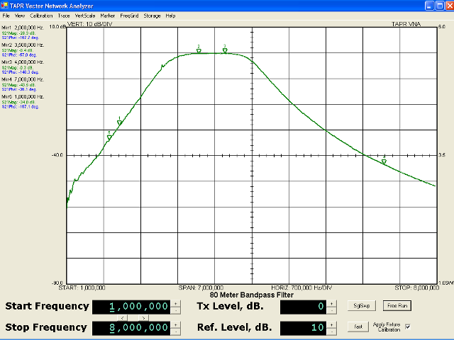
Figure 7: Attenuation vs. frequency [full resolution version]
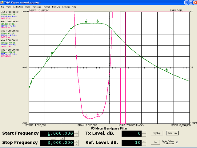
Figure 8: SWR vs. frequency [full resolution version]
Updated $Date: 2008-08-31 15:20:02 +0000 (Sun, 31 Aug 2008) $